ArduinoでLCDに表示させる [Arduino]
これまでArduinoからの出力はシリアルでPCを経由してモニタに出力していました。Serial.print()ってやつね。
いつまでもPCモニタに頼るわけにはいきませんので、今回はArduinoから文字を液晶ディスプレイ(LCD)にて表示させたいと思います。
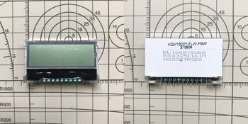
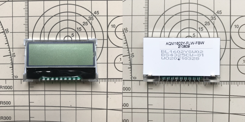
使うのは、16×2行のキャラクタLCDモジュール、バックライト付きです。
これです↓
LCD16×2行 白色バックライト付 AQM1602Y-FLW-FBW
"https://akizukidenshi.com/catalog/g/gP-12619/"
インタフェースはI2C接続で、液晶コントローラはST7032iです。電源電圧は5V動作も可能なようですが、推奨の3.3Vで動作させることにしました。
ユニバーサル基板へLCDモジュールを実装します。
回路図とPCBEで作成した実装図を示します。
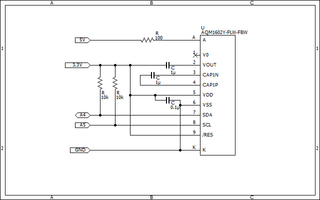
【回路図】
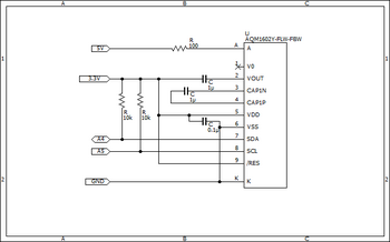
回路図の各値はマニュアルを参考に設計しましたが、バックライトの抵抗は計算して100[Ω]としています。マニュアルを読むと順電圧Vf=3.1[V]、順電流If=30[mA]となっていたので、バックライトにかける電源電圧を5[V]とした場合、
5.0 - 3.1 = 1.9[V] 1.9 / 30×1E-3 = 63.3[Ω] 手持ちの近い抵抗100[Ω]に決定です!
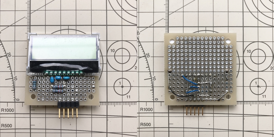
【実装図】
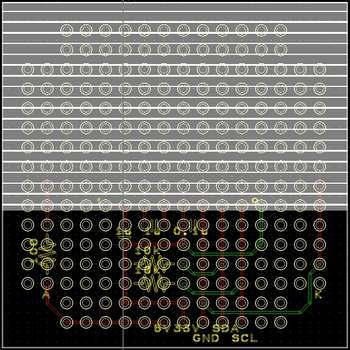
白色で塗り潰してある領域はLCDモジュールが載る部分をマークしています。(配置配線不可)。
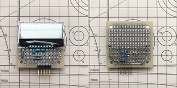
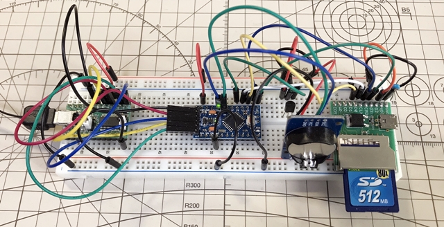
実際にユニバーサル基板上に実装した写真です。事前にPCBEで実装図を作成していたので、きれいに収まりました。
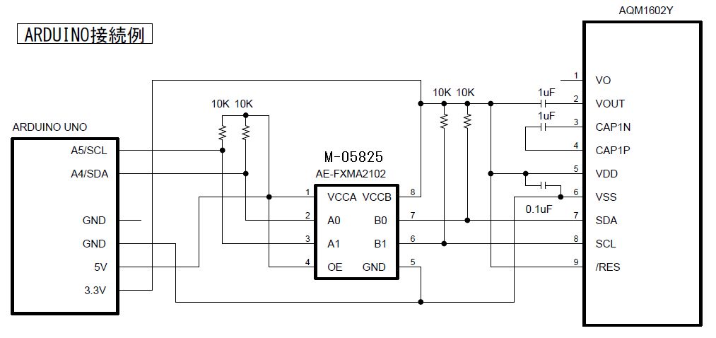
【配線図】
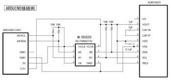
マニュアルに掲載されているArduino UNOとの接続例そのままの配線図です。
UNOは5[V]でLCDモジュールは3.3[V]のため、SDAとSCL信号にはUNOとLCDモジュールの間に電圧レベル変換モジュールを挟んでいます。
I2Cバス用双方向電圧レベル変換モジュール(FXMA2102)
"https://akizukidenshi.com/catalog/g/gM-05825/"
【スケッチ】
動作確認用のテストスケッチは、秋月のAQM1602XA-RN-GBWの取説に掲載のArduino用のプログラムを少し変更を加えたものです。
"https://akizukidenshi.com/catalog/g/gP-08779/"
LCDのスレーブアドレス( LCD_ADRS = 0x3E)は以下のArduino IDEのスケッチ例にあるスケッチを使うことで確認することができますので、確認後実物のアドレスと書き換えてください。
ファイル>スケッチ例>Wire>i2c_scanner

いつまでもPCモニタに頼るわけにはいきませんので、今回はArduinoから文字を液晶ディスプレイ(LCD)にて表示させたいと思います。
使うのは、16×2行のキャラクタLCDモジュール、バックライト付きです。
これです↓
LCD16×2行 白色バックライト付 AQM1602Y-FLW-FBW
"https://akizukidenshi.com/catalog/g/gP-12619/"
インタフェースはI2C接続で、液晶コントローラはST7032iです。電源電圧は5V動作も可能なようですが、推奨の3.3Vで動作させることにしました。
ユニバーサル基板へLCDモジュールを実装します。
回路図とPCBEで作成した実装図を示します。
【回路図】
回路図の各値はマニュアルを参考に設計しましたが、バックライトの抵抗は計算して100[Ω]としています。マニュアルを読むと順電圧Vf=3.1[V]、順電流If=30[mA]となっていたので、バックライトにかける電源電圧を5[V]とした場合、
5.0 - 3.1 = 1.9[V] 1.9 / 30×1E-3 = 63.3[Ω] 手持ちの近い抵抗100[Ω]に決定です!
【実装図】

白色で塗り潰してある領域はLCDモジュールが載る部分をマークしています。(配置配線不可)。
実際にユニバーサル基板上に実装した写真です。事前にPCBEで実装図を作成していたので、きれいに収まりました。
【配線図】
マニュアルに掲載されているArduino UNOとの接続例そのままの配線図です。
UNOは5[V]でLCDモジュールは3.3[V]のため、SDAとSCL信号にはUNOとLCDモジュールの間に電圧レベル変換モジュールを挟んでいます。
I2Cバス用双方向電圧レベル変換モジュール(FXMA2102)
"https://akizukidenshi.com/catalog/g/gM-05825/"
【スケッチ】
動作確認用のテストスケッチは、秋月のAQM1602XA-RN-GBWの取説に掲載のArduino用のプログラムを少し変更を加えたものです。
"https://akizukidenshi.com/catalog/g/gP-08779/"
LCDのスレーブアドレス( LCD_ADRS = 0x3E)は以下のArduino IDEのスケッチ例にあるスケッチを使うことで確認することができますので、確認後実物のアドレスと書き換えてください。
ファイル>スケッチ例>Wire>i2c_scanner
/******************************************************************************* I2Cキャラクタ液晶(ST7032i)の動作テスト用プログラム ・駆動用IC:ST7032i ・インタフェース:I2C ・電源電圧=3.3V, SCL=A5, SDA=A4 *******************************************************************************/ #include#define LCD_ADRS 0x3E char moji[] = "AQM1602Y-FLW-FBW"; //SCL=A5=LCDNo2 SDA=A4=LCDNo3 void setup() { Wire.begin(); init_LCD(); //液晶(ST7032i)初期化 } void loop() { for (int i = 0; i < 16; i++) { writeData(moji[i]); //文字列表示 } writeCommand(0x40+0x80); //2行目先頭 for (int i = 0; i < 16; i++) { writeData(i+0xb1); } while(1){}//stop } //----main end---- //データ書き込み void writeData(byte t_data){ Wire.beginTransmission(LCD_ADRS); Wire.write(0x40); Wire.write(t_data); Wire.endTransmission(); delay(1); } //コマンド書き込み void writeCommand(byte t_command) { Wire.beginTransmission(LCD_ADRS); Wire.write(0x00); Wire.write(t_command); Wire.endTransmission(); delay(10); } //液晶(ST7032i)初期化 void init_LCD() { delay(100); writeCommand(0x38); // FUNCTION SET delay(20); writeCommand(0x39); // FUNCTION SET(IS=1) delay(20); writeCommand(0x14); // Internal OSC freq. delay(20); writeCommand(0x73); // Contrast set(上位と合わせて0x23) delay(20); writeCommand(0x56); // Power/ION/Contrast control(Bon ON,3.3V用) //writeCommand(0x52); // Power/ION/Contrast control(Bon OFF,5V用) delay(20); writeCommand(0x6C); // Follower control delay(20); writeCommand(0x38); // FUNCTION SET(IS=0) delay(20); writeCommand(0x01); // Clear Display delay(20); writeCommand(0x0C); // Display ON/OFF control delay(20); }
Arduinoでデータロガーを作る【温度センサ+SDカード+RTC】 [Arduino]
これまでで、
#Arduinoでデータロガーを作る【温度センサ+SDカード】
#ArduinoでRTCを使う
ができたので、これらを一つにまとめてタイムスタンプとセットでデータを保存できるようにしたいと思います。
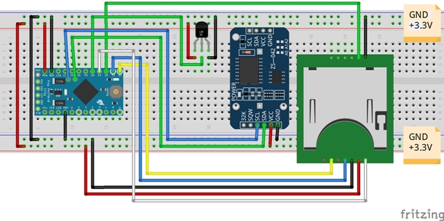
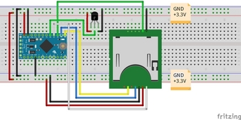
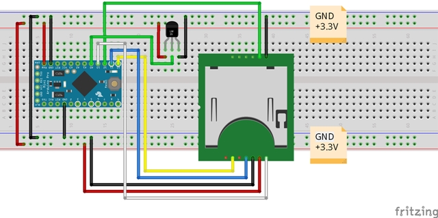
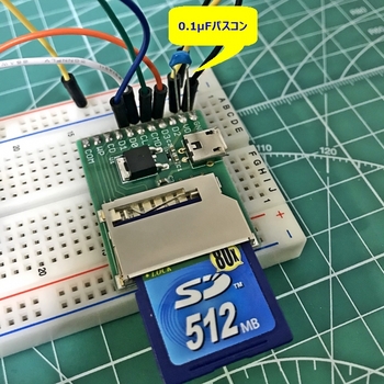
【配線図】
Fritzingの配線図では省略してしまったのですが、RTCのVCCとGNDには0.1μFのパスコンが接続してあります。ブレッドボードやジャンプワイヤのせいもあるかもしれませんが、動作が不安定だったのでパスコンはあった方がいいと思います。
あと、SDカード配線引出基板と電源とGNDの間のパスコンも。#ArduinoでSDカード情報を取得する


【スケッチ】
これで、タイムスタンプと温度データを一緒にSDカードのファイルに保存することができました。
#Arduinoでデータロガーを作る【温度センサ+SDカード】
#ArduinoでRTCを使う
ができたので、これらを一つにまとめてタイムスタンプとセットでデータを保存できるようにしたいと思います。
【配線図】
Fritzingの配線図では省略してしまったのですが、RTCのVCCとGNDには0.1μFのパスコンが接続してあります。ブレッドボードやジャンプワイヤのせいもあるかもしれませんが、動作が不安定だったのでパスコンはあった方がいいと思います。
あと、SDカード配線引出基板と電源とGNDの間のパスコンも。#ArduinoでSDカード情報を取得する
【スケッチ】
/******************************************************************************* SDカードデータロガー ++++++ note ++++++ ・測定した温度をコンソール画面に表示およびSDカードにデータ保存するプログラム ・Arduino Pro Mini(3.3V, 8MHz) ・温度センサ LM61BIZ(測定範囲:-25℃~+85℃) ・(※)RTCから取得した現在の日時データをSDカードファイル書き込みとコンソール画面表示に使う *******************************************************************************/ #include#include #include "RTClib.h" //RTCライブラリを導入 File myFile; //Fileオブジェクトの生成(インスタンス名:myFile) RTC_DS3231 rtc; //RTCオブジェクトの生成(インスタンス名:rtc) const float Vcc = 3.3; //電源電圧(定数) float temp_volt; //出力電圧 float temp_data; //温度 char daysOfTheWeek[7][6] = {"Sun.", "Mon.", "Tue.", "Wed.", "Thu.", "Fri.", "Sat."}; String youbi; //曜日を代入する int year, month, day, hour, minute, second; // the setup routine runs once when you press reset:初期化(電源投入/リセット時1回のみ実行) void setup() { // Open serial communications and wait for port to open: Serial.begin(9600); //9600bpsでシリアルポートを開く while (!Serial) { ; // wait for serial port to connect. Needed for native USB port only } //RTCオブジェクトの初期化 if (! rtc.begin()) { //RTCオブジェクトに初期化に失敗 Serial.println("Couldn't find RTC"); Serial.flush(); abort(); } //RTCオブジェクトに初期化に成功 // rtc.adjust(DateTime(F(__DATE__), F(__TIME__))); //今の(PCの)時刻に合わせる // →合わせ終わったらコメントアウトすること //SDカードの初期設定 Serial.print("Initializing SD card..."); if (!SD.begin(10)) { //4→10に変更 SDカードの初期化に失敗 Serial.println("initialization failed!"); while (1); } //SDカードの初期化に成功 Serial.println("initialization done."); } // the loop routine runs over and over again forever: main loop void loop() { int sensorValue = analogRead(A0); //read the input on analog pin 0: temp_volt = Vcc * sensorValue / 1023; //アナログピンから読み取った値を元の出力電圧値に戻す // 出力電圧から温度データを作成 temp_data = (temp_volt - 0.6) / 0.01; //【データシート】T[℃] = (Vo - 0.6) / 0.01 // RTCから現在の日時を取得(※) DateTime now = rtc.now(); year = now.year(); month = now.month(); day = now.day(); youbi = daysOfTheWeek[now.dayOfTheWeek()]; hour = now.hour(); minute = now.minute(); second = now.second(); // RTCの日時と温度データをコンソール画面に表示(※) // ①float(浮動小数点)形式で表示 Serial.print(year); //RTCの日時を表示 Serial.print('/'); Serial.print(month); Serial.print('/'); Serial.print(day); Serial.print('('); Serial.print(youbi); Serial.print(')'); Serial.print(hour); Serial.print(':'); Serial.print(minute); Serial.print(':'); Serial.print(second); Serial.print(" "); //tab(空欄)はダブルクォーテーションで囲む Serial.print(temp_data); //温度を表示 Serial.println("[℃]"); //単位は℃ // SDカードに書き込む // open the file. note that only one file can be open at a time, // so you have to close this one before opening another. myFile = SD.open("tempdata.txt", FILE_WRITE); //"tempdata.txt"ファイルを書き込み用に開く //戻り値がファイル情報になり、myFile に受け渡す // ファイルに温度データを書き込み(※) // if the file opened okay, write to it: if (myFile) { // ①float(浮動小数点)形式で書き込み myFile.print(year); myFile.print('/'); myFile.print(month); myFile.print('/'); myFile.print(day); myFile.print('('); myFile.print(youbi); myFile.print(')' ); myFile.print(hour); myFile.print(':'); myFile.print(minute); myFile.print(':'); myFile.print(second); myFile.print(" "); //tab(空欄)はダブルクォーテーションで囲む myFile.print(temp_data); myFile.println("[℃]"); // close the file: myFile.close(); //ファイルを閉じる //myFile.close() Fileオブジェクト(インスタンス)に対する関数 } else { // if the file didn't open, print an error: Serial.println("error opening tempdata.txt"); } delay(1000); //1秒単位 ※delay():単位ms }
これで、タイムスタンプと温度データを一緒にSDカードのファイルに保存することができました。
ArduinoでRTCを使う [Arduino]
前回に、#Arduinoでデータロガーを作る【温度センサ+SDカード】
>なので、次はRTCを使ってタイムスタンプとセットでデータを保存できるようにしたいと思います。
と書いたので、RTCを試してみたいと思います。
Amazonは電子部品のレパートリーも豊富で入手性も良く、送料無料の物も多いので、重宝しています。
DS3231 AT24C32 時計モジュール リアル時間時計モジュール IICモジュール RTCモジュール に対応(3個セット)
"https://www.amazon.co.jp/AT24C32-%E3%83%AA%E3%82%A2%E3%83%AB%E6%99%82%E9%96%93%E6%99%82%E8%A8%88%E3%83%A2%E3%82%B8%E3%83%A5%E3%83%BC%E3%83%AB-IIC%E3%83%A2%E3%82%B8%E3%83%A5%E3%83%BC%E3%83%AB-RTC%E3%83%A2%E3%82%B8%E3%83%A5%E3%83%BC%E3%83%AB-Arduino%E3%81%AB%E5%AF%BE%E5%BF%9C/dp/B0793MNVR4/ref=pd_ybh_a_4?_encoding=UTF8&psc=1&refRID=D02CJTZ6E9CCYEBD410S"
★注意★
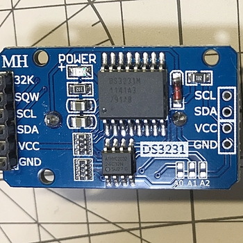
「DS3231」にはいくつかの種類があるようです。
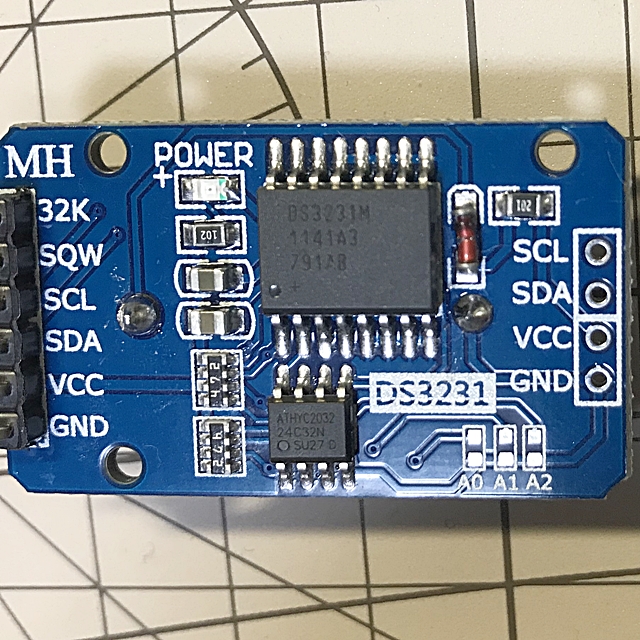
今回購入したRTCモジュールに搭載されていたのは「DS3231M」でした。
「DS3231M」はTCXOではなくMEMS共振子で、周波数精度も±2ppm→±5ppmと残念ながらやや劣るようです。。。3個で890円だったからかなー。安いとチップが違うのかなー。
充電式リチウムイオンボタン電池 LIR2032 3.6V 40mAh 約500回 CR2032の代わり 5枚入1セット
"https://www.amazon.co.jp/%E5%85%85%E9%9B%BB%E5%BC%8F%E3%83%AA%E3%83%81%E3%82%A6%E3%83%A0%E3%82%A4%E3%82%AA%E3%83%B3%E3%83%9C%E3%82%BF%E3%83%B3%E9%9B%BB%E6%B1%A0-LIR2032-40mAh-CR2032%E3%81%AE%E4%BB%A3%E3%82%8F%E3%82%8A-5%E6%9E%9A%E5%85%A5%EF%BC%91%E3%82%BB%E3%83%83%E3%83%88/dp/B08FHWQBBK/ref=pd_ybh_a_2?_encoding=UTF8&psc=1&refRID=D02CJTZ6E9CCYEBD410S"
コイン電池充電器
"https://www.amazon.co.jp/Entatial-%E5%B0%8F%E5%9E%8B%E3%83%9C%E3%83%87%E3%82%A3%E4%BF%A1%E9%A0%BC%E6%80%A7%E3%81%AE%E9%AB%98%E3%81%84%E3%83%9C%E3%82%BF%E3%83%B3%E9%9B%BB%E6%B1%A0%E5%85%85%E9%9B%BB%E5%99%A8%E3%80%81%E5%85%85%E9%9B%BB%E5%99%A8%E3%80%81%E6%8C%81%E3%81%A1%E9%81%8B%E3%81%B3%E3%81%8C%E7%B0%A1%E5%8D%98%E9%9B%BB%E6%B1%A0%E5%85%85%E9%9B%BB%E7%94%A8%E3%81%AE%E5%AE%89%E5%AE%9A%E3%81%97%E3%81%9F%E6%80%A7%E8%83%BD%E3%82%B3%E3%82%A4%E3%83%B3%E9%9B%BB%E6%B1%A0%E5%85%85%E9%9B%BB%E5%99%A8-U-S-regulations/dp/B08NF7YTFM/ref=psdc_2285180051_t1_B08NDVRMH1"
LIR2032ボタン(コイン)電池の充電用に1個買ったのですが2個届きました。
でも、そのうちの1個は動作不良でした。。。
中華製は、時々想定外のことが起こりますねー(笑)
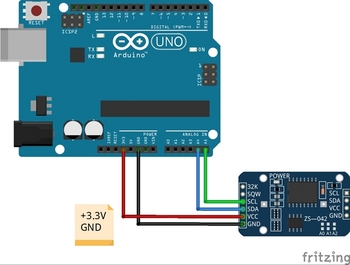
まずは単体で動作させてみたいと思います。
時刻データをコンソール画面に出力します。
ネットでググれば、この程度の情報はたくさんあるのでサクサクと進めたいと思います。
【配線図】
【スケッチ】
ネット情報により、ご多分に漏れず、ライブラリーをDLしてインクルードします。
DS3231で使用可能なライブラリは複数あるようですが、Arduino IDEのライブラリ管理でヒットした、
RTCLib (Adafruit)をそのまま使います。
コンパイルしてArduinoに書き込んだ後に、Arduino IDEのシリアルモニタを確認すると、
3秒に1回、時刻データが更新されていきます。
■時刻アジャストについて
手持ちの電波時計と比較すると、時刻データが1分ほど遅れていました。
これは、
rtc.adjust(DateTime(F(__DATE__), F(__TIME__)));
にて、今の(PCの)時刻に合わせるようにしているのですが、コンパイルにかかる時間分がずれてしまうためだそうです。
ネットでは、時刻合わせのための治具を作成して調整されている記事もありましたので、機会があったら挑戦してみたいと思います。
今回は、単体での動作を優先したく、そこまでの調整はしませんでしたが、コンパイルにかかる時間を短くすれば誤差は小さくなると思いますので、先ほどのスケッチから余計なプログラムを削除してなるべく軽くしたものを、時刻合わせ用のスケッチとして再作成しておきました。
>なので、次はRTCを使ってタイムスタンプとセットでデータを保存できるようにしたいと思います。
と書いたので、RTCを試してみたいと思います。
Amazonは電子部品のレパートリーも豊富で入手性も良く、送料無料の物も多いので、重宝しています。
DS3231 AT24C32 時計モジュール リアル時間時計モジュール IICモジュール RTCモジュール に対応(3個セット)
"https://www.amazon.co.jp/AT24C32-%E3%83%AA%E3%82%A2%E3%83%AB%E6%99%82%E9%96%93%E6%99%82%E8%A8%88%E3%83%A2%E3%82%B8%E3%83%A5%E3%83%BC%E3%83%AB-IIC%E3%83%A2%E3%82%B8%E3%83%A5%E3%83%BC%E3%83%AB-RTC%E3%83%A2%E3%82%B8%E3%83%A5%E3%83%BC%E3%83%AB-Arduino%E3%81%AB%E5%AF%BE%E5%BF%9C/dp/B0793MNVR4/ref=pd_ybh_a_4?_encoding=UTF8&psc=1&refRID=D02CJTZ6E9CCYEBD410S"
★注意★
「DS3231」にはいくつかの種類があるようです。
今回購入したRTCモジュールに搭載されていたのは「DS3231M」でした。
「DS3231M」はTCXOではなくMEMS共振子で、周波数精度も±2ppm→±5ppmと残念ながらやや劣るようです。。。3個で890円だったからかなー。安いとチップが違うのかなー。
充電式リチウムイオンボタン電池 LIR2032 3.6V 40mAh 約500回 CR2032の代わり 5枚入1セット
"https://www.amazon.co.jp/%E5%85%85%E9%9B%BB%E5%BC%8F%E3%83%AA%E3%83%81%E3%82%A6%E3%83%A0%E3%82%A4%E3%82%AA%E3%83%B3%E3%83%9C%E3%82%BF%E3%83%B3%E9%9B%BB%E6%B1%A0-LIR2032-40mAh-CR2032%E3%81%AE%E4%BB%A3%E3%82%8F%E3%82%8A-5%E6%9E%9A%E5%85%A5%EF%BC%91%E3%82%BB%E3%83%83%E3%83%88/dp/B08FHWQBBK/ref=pd_ybh_a_2?_encoding=UTF8&psc=1&refRID=D02CJTZ6E9CCYEBD410S"
コイン電池充電器
"https://www.amazon.co.jp/Entatial-%E5%B0%8F%E5%9E%8B%E3%83%9C%E3%83%87%E3%82%A3%E4%BF%A1%E9%A0%BC%E6%80%A7%E3%81%AE%E9%AB%98%E3%81%84%E3%83%9C%E3%82%BF%E3%83%B3%E9%9B%BB%E6%B1%A0%E5%85%85%E9%9B%BB%E5%99%A8%E3%80%81%E5%85%85%E9%9B%BB%E5%99%A8%E3%80%81%E6%8C%81%E3%81%A1%E9%81%8B%E3%81%B3%E3%81%8C%E7%B0%A1%E5%8D%98%E9%9B%BB%E6%B1%A0%E5%85%85%E9%9B%BB%E7%94%A8%E3%81%AE%E5%AE%89%E5%AE%9A%E3%81%97%E3%81%9F%E6%80%A7%E8%83%BD%E3%82%B3%E3%82%A4%E3%83%B3%E9%9B%BB%E6%B1%A0%E5%85%85%E9%9B%BB%E5%99%A8-U-S-regulations/dp/B08NF7YTFM/ref=psdc_2285180051_t1_B08NDVRMH1"
LIR2032ボタン(コイン)電池の充電用に1個買ったのですが2個届きました。
でも、そのうちの1個は動作不良でした。。。
中華製は、時々想定外のことが起こりますねー(笑)
まずは単体で動作させてみたいと思います。
時刻データをコンソール画面に出力します。
ネットでググれば、この程度の情報はたくさんあるのでサクサクと進めたいと思います。
【配線図】

【スケッチ】
ネット情報により、ご多分に漏れず、ライブラリーをDLしてインクルードします。
DS3231で使用可能なライブラリは複数あるようですが、Arduino IDEのライブラリ管理でヒットした、
RTCLib (Adafruit)をそのまま使います。
/*******************************************************************************
RTC(DS3231) サンプルプログラム

++++++ note ++++++

*******************************************************************************/
// Date and time functions using a DS3231 RTC connected via I2C and Wire lib
#include "RTClib.h"                                 //RTCライブラリを導入

RTC_DS3231 rtc;                                     //RTCオブジェクトの生成(インスタンス名:rtc)

char daysOfTheWeek[7][12] = {"Sunday", "Monday", "Tuesday", "Wednesday", "Thursday", "Friday", "Saturday"};

void setup () {
  Serial.begin(9600);                               //9600bpsでシリアルポートを開く

#ifndef ESP8266    //【条件コンパイル】 もしESP8266が定義されていなかったら
  while (!Serial); // wait for serial port to connect. Needed for native USB
                   //(シリアルポートが接続するのを待ちます。 ネイティブUSBに必要)
#endif
//RTCオブジェクトの初期化
  if (! rtc.begin()) {                              //RTCオブジェクトに初期化に失敗
    Serial.println("Couldn't find RTC");
    Serial.flush();
    abort();
  }                                                 //RTCオブジェクトに初期化に成功
  rtc.adjust(DateTime(F(__DATE__), F(__TIME__)));   //今の(PCの)時刻に合わせる
                                                    //合わせ終わったらコメントアウトする
  if (rtc.lostPower()) {
    Serial.println("RTC lost power, let's set the time!");
    // When time needs to be set on a new device, or after a power loss, the
    // following line sets the RTC to the date & time this sketch was compiled
    rtc.adjust(DateTime(F(__DATE__), F(__TIME__)));
    // This line sets the RTC with an explicit date & time, for example to set
    // January 21, 2014 at 3am you would call:
    // rtc.adjust(DateTime(2014, 1, 21, 3, 0, 0));
  }

  // When time needs to be re-set on a previously configured device, the
  // following line sets the RTC to the date & time this sketch was compiled
  // rtc.adjust(DateTime(F(__DATE__), F(__TIME__)));
  // This line sets the RTC with an explicit date & time, for example to set
  // January 21, 2014 at 3am you would call:
  // rtc.adjust(DateTime(2014, 1, 21, 3, 0, 0));
}

void loop () {
    DateTime now = rtc.now();

    Serial.print(now.year(), DEC);
    Serial.print('/');
    Serial.print(now.month(), DEC);
    Serial.print('/');
    Serial.print(now.day(), DEC);
    Serial.print(" (");
    Serial.print(daysOfTheWeek[now.dayOfTheWeek()]);
    Serial.print(") ");
    Serial.print(now.hour(), DEC);
    Serial.print(':');
    Serial.print(now.minute(), DEC);
    Serial.print(':');
    Serial.print(now.second(), DEC);
    Serial.println();

    Serial.print(" since midnight 1/1/1970 = ");
    Serial.print(now.unixtime());
    Serial.print("s = ");
    Serial.print(now.unixtime() / 86400L);
    Serial.println("d");

    // calculate a date which is 7 days, 12 hours, 30 minutes, 6 seconds into the future
    DateTime future (now + TimeSpan(7,12,30,6));

    Serial.print(" now + 7d + 12h + 30m + 6s: ");
    Serial.print(future.year(), DEC);
    Serial.print('/');
    Serial.print(future.month(), DEC);
    Serial.print('/');
    Serial.print(future.day(), DEC);
    Serial.print(' ');
    Serial.print(future.hour(), DEC);
    Serial.print(':');
    Serial.print(future.minute(), DEC);
    Serial.print(':');
    Serial.print(future.second(), DEC);
    Serial.println();

    Serial.print("Temperature: ");
    Serial.print(rtc.getTemperature());
    Serial.println(" C");

    Serial.println();
    delay(3000);
}
コンパイルしてArduinoに書き込んだ後に、Arduino IDEのシリアルモニタを確認すると、
3秒に1回、時刻データが更新されていきます。
■時刻アジャストについて
手持ちの電波時計と比較すると、時刻データが1分ほど遅れていました。
これは、
rtc.adjust(DateTime(F(__DATE__), F(__TIME__)));
にて、今の(PCの)時刻に合わせるようにしているのですが、コンパイルにかかる時間分がずれてしまうためだそうです。
ネットでは、時刻合わせのための治具を作成して調整されている記事もありましたので、機会があったら挑戦してみたいと思います。
今回は、単体での動作を優先したく、そこまでの調整はしませんでしたが、コンパイルにかかる時間を短くすれば誤差は小さくなると思いますので、先ほどのスケッチから余計なプログラムを削除してなるべく軽くしたものを、時刻合わせ用のスケッチとして再作成しておきました。
Arduinoでデータロガーを作る【温度センサ+SDカード】 [Arduino]
前回までで、
・SDカードにファイルを読み書きする #ArduinoでSDカードにファイルを読み書きする
・温度を測定する #Arduinoで温度を測る【温度センサ】
ことができましたので、これを組み合わせて温度データをSDカードに書き込むデータロガーを作りたいと思います。
【配線図】
【スケッチ】
ネットも参考にすると、もう少しスマートな記述もありますが、今の自分の理解レベルと少々乖離している感もあったので、まずはベタな書き方ですが載せてみます。
今後スキルが上がれば、改版したいと思っています。
①float(浮動小数点)形式、②String(文字列)形式の両方を記述していますが、下記では①をコメントアウトして、②を有効にしています。
上記でもデータは保存できたのですが、少々残念なことに、データを取得したタイムスタンプが無いんですねー。。。
なので、次はRTCを使ってタイムスタンプとセットでデータを保存できるようにしたいと思います。
・SDカードにファイルを読み書きする #ArduinoでSDカードにファイルを読み書きする
・温度を測定する #Arduinoで温度を測る【温度センサ】
ことができましたので、これを組み合わせて温度データをSDカードに書き込むデータロガーを作りたいと思います。
【配線図】
【スケッチ】
ネットも参考にすると、もう少しスマートな記述もありますが、今の自分の理解レベルと少々乖離している感もあったので、まずはベタな書き方ですが載せてみます。
今後スキルが上がれば、改版したいと思っています。
①float(浮動小数点)形式、②String(文字列)形式の両方を記述していますが、下記では①をコメントアウトして、②を有効にしています。
/******************************************************************************* SDカードデータロガー ++++++ note ++++++ ・測定した温度をコンソール画面に表示およびSDカードにデータ保存するプログラム ・Arduino Pro Mini(3.3V, 8MHz) ・温度センサ LM61BIZ(測定範囲:-25℃~+85℃) ・①float(浮動小数点)形式でも②String(文字列)形式でも出力結果は同じ *******************************************************************************/ #include#include File myFile; const float Vcc = 3.3; //電源電圧(定数) float temp_volt; //出力電圧 float temp_data; //温度 // the setup routine runs once when you press reset:初期化(電源投入/リセット時1回のみ実行) void setup() { // Open serial communications and wait for port to open: Serial.begin(9600); //9600bpsでシリアルポートを開く while (!Serial) { ; // wait for serial port to connect. Needed for native USB port only } //SDカードの初期設定 Serial.print("Initializing SD card..."); if (!SD.begin(10)) { //4→10に変更 Serial.println("initialization failed!"); while (1); } Serial.println("initialization done."); } // the loop routine runs over and over again forever: main loop void loop() { int sensorValue = analogRead(A0); //read the input on analog pin 0: temp_volt = Vcc * sensorValue / 1023; //アナログピンから読み取った値を元の出力電圧値に戻す // 出力電圧から温度データを作成 temp_data = (temp_volt - 0.6) / 0.01; //【データシート】T[℃] = (Vo - 0.6) / 0.01 // 温度データをコンソール画面に表示 ※2種類記載 /* ①float(浮動小数点)形式で表示 Serial.print(temp_data); //温度を表示 Serial.println("[℃]"); //単位は℃ */ // ②String(文字列)形式で表示 String dataString = ""; dataString += String(temp_data); dataString += "[℃]"; Serial.println(dataString); //温度を表示、単位は℃ // SDカードに書き込む // open the file. note that only one file can be open at a time, // so you have to close this one before opening another. myFile = SD.open("tempdata.txt", FILE_WRITE); //"tempdata.txt"ファイルを書き込み用に開く //戻り値がファイル情報になり、myFile に受け渡す // ファイルに温度データを書き込み ※2種類記載 // if the file opened okay, write to it: if (myFile) { /* ①float(浮動小数点)形式で書き込み myFile.print(temp_data); myFile.println("[℃]"); */ // ②文字列(String)で書き込み myFile.println(dataString); // close the file: myFile.close(); //ファイルを閉じる } else { // if the file didn't open, print an error: Serial.println("error opening tempdata.txt"); } delay(1000); //1秒単位 ※delay():単位ms }
上記でもデータは保存できたのですが、少々残念なことに、データを取得したタイムスタンプが無いんですねー。。。
なので、次はRTCを使ってタイムスタンプとセットでデータを保存できるようにしたいと思います。
Arduinoで温度を測る [Arduino]
Arduinoで温度を測ります!
使うのは、温度センサの「LM61BIZ」です。
これです↓
高精度IC温度センサLM61BIZ
.JPG)
※以前に秋月電子で購入したのですが、メーカ都合により現在では販売されていないようです。
TI社の半導体製品が生産終了でないのに在庫限りです。どうしてですか?/TIのIC単体を購入できませんがどうしてですか?
"https://akizukidenshi.com/catalog/faq/goodsfaq.aspx?goods=I-09691"
【配線図】
【スケッチ】
データシートを見ると
Vo = (+10mV/℃ × T℃)+ 600mV
とありますので、温度T℃を求めるためには、
T℃ = (Vo - 0.6[V]) / 0.01[V]
で求まります。
スケッチは以前に赤外線測距センサで作成したものを少し修正すればOKです。
使うのは、温度センサの「LM61BIZ」です。
これです↓
高精度IC温度センサLM61BIZ
.JPG)
※以前に秋月電子で購入したのですが、メーカ都合により現在では販売されていないようです。
TI社の半導体製品が生産終了でないのに在庫限りです。どうしてですか?/TIのIC単体を購入できませんがどうしてですか?
"https://akizukidenshi.com/catalog/faq/goodsfaq.aspx?goods=I-09691"
【配線図】

【スケッチ】
データシートを見ると
Vo = (+10mV/℃ × T℃)+ 600mV
とありますので、温度T℃を求めるためには、
T℃ = (Vo - 0.6[V]) / 0.01[V]
で求まります。
スケッチは以前に赤外線測距センサで作成したものを少し修正すればOKです。
/*
  AnalogReadSerial

  Reads an analog input on pin 0, prints the result to the Serial Monitor.
  Graphical representation is available using Serial Plotter (Tools > Serial Plotter menu).
  Attach the center pin of a potentiometer to pin A0, and the outside pins to +5V and ground.

  This example code is in the public domain.

  http://www.arduino.cc/en/Tutorial/AnalogReadSerial
*/
/*******************************************************************************
温度センサ(LM61BIZ) サンプルプログラム
++++++ note ++++++
・温度センサ LM61BIZ
・測定した温度をコンソール画面に表示するプログラム
・測定範囲:-25℃~+85℃

*******************************************************************************/
const float Vcc = 3.3;                   //電源電圧(定数)
float temp_volt;                         //出力電圧
float temp_data;                         //温度

// the setup routine runs once when you press reset:初期化(電源投入/リセット時1回のみ実行)
void setup() {
  // initialize serial communication at 9600 bits per second:
  Serial.begin(9600);                    //9600bpsでシリアルポートを開く
}

// the loop routine runs over and over again forever: main loop
void loop() {
  int sensorValue = analogRead(A0);      //read the input on analog pin 0:
  temp_volt = Vcc * sensorValue / 1023;  //アナログピンから読み取った値を元の出力電圧値に戻す

// 出力電圧から温度データを作成
  temp_data = (temp_volt - 0.6) / 0.01;  //【データシート】T[℃] = (Vo - 0.6) / 0.01

// 温度データの表示 temp_dataの値をハード・シリアルへ出力する(Arduino→PCモニタ)
  Serial.print(temp_data);               //温度を表示
  Serial.println("[℃]");                //単位は℃
  delay(1000);                           //1秒単位(シリアルポートを溢れさせないように) ※delay():単位ms
}
ArduinoでGPS情報を取得する [Arduino]
SDカードシリーズはいろいろと物品調達の準備があるため、その間に別のことやりたいと思います。
”ArduinoでGPS情報を取得する”です。
これもいずれはやっておきたかったことなので、このタイミングで試してみたいと思います。
GPSモジュールは秋月電子のを使います。
ググると、たくさんの製作記事がヒットするので情報には困らないと思います。
GPS受信機キット 1PPS出力付き「みちびき」3機受信対応

"https://akizukidenshi.com/catalog/g/gK-09991/"
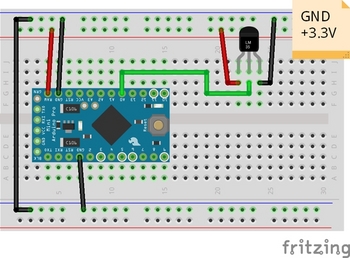
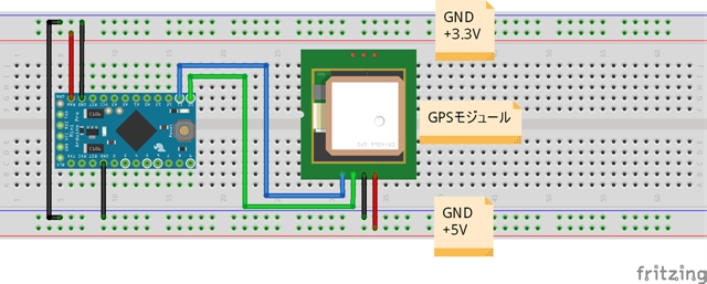
GPSモジュールの電源は5Vですが、データIOは3.3Vです。そのため今回はArduino Pro Mini(3.3V, 8MHz)を使います。
【配線図】

【スケッチ】
最初にGPSモジュールからの情報をコンソール画面に表示する、サンプルスケッチを試してみます。
Arduino IDEから
ファイル>スケッチ例>SoftwareSerial>SoftwareSerialExample
シアルポートのデータ転送レートを変更しています。
もちろん、シリアルモニタともデータ転送レートは一致させるのですが、9600以外では文字化けしてしまい、うまく表示することが出来ませんでした。
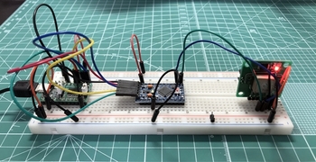
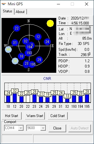
電源を入れるとLEDが点灯してGPSを捕捉し始めます。
コールドスタートと言って、まっさらな状態からだと40~90秒くらいでGPSを捕捉するようです。捕捉できたらLEDは1秒周期で点滅を始めます。
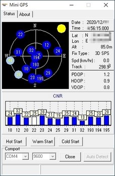
キットに付属のソフトウェア(MiniGPS)でデータを受けると、捕捉したGPSの数や緯度経度、時刻とかの情報を表示させることができます。
”ArduinoでGPS情報を取得する”です。
これもいずれはやっておきたかったことなので、このタイミングで試してみたいと思います。
GPSモジュールは秋月電子のを使います。
ググると、たくさんの製作記事がヒットするので情報には困らないと思います。
GPS受信機キット 1PPS出力付き「みちびき」3機受信対応
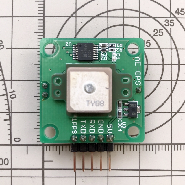
"https://akizukidenshi.com/catalog/g/gK-09991/"
GPSモジュールの電源は5Vですが、データIOは3.3Vです。そのため今回はArduino Pro Mini(3.3V, 8MHz)を使います。
【配線図】

【スケッチ】
最初にGPSモジュールからの情報をコンソール画面に表示する、サンプルスケッチを試してみます。
Arduino IDEから
ファイル>スケッチ例>SoftwareSerial>SoftwareSerialExample
シアルポートのデータ転送レートを変更しています。
もちろん、シリアルモニタともデータ転送レートは一致させるのですが、9600以外では文字化けしてしまい、うまく表示することが出来ませんでした。
/* Software serial multple serial test Receives from the hardware serial, sends to software serial. Receives from software serial, sends to hardware serial. The circuit: * RX is digital pin 10 (connect to TX of other device) * TX is digital pin 11 (connect to RX of other device) Note: Not all pins on the Mega and Mega 2560 support change interrupts, so only the following can be used for RX: 10, 11, 12, 13, 50, 51, 52, 53, 62, 63, 64, 65, 66, 67, 68, 69 Not all pins on the Leonardo and Micro support change interrupts, so only the following can be used for RX: 8, 9, 10, 11, 14 (MISO), 15 (SCK), 16 (MOSI). created back in the mists of time modified 25 May 2012 by Tom Igoe based on Mikal Hart's example This example code is in the public domain. */ /******************************************************************************* GPSテスト用シリアル通信プログラム ++++++ note ++++++ ・Arduino Pro Mini使用 ・スケッチデフォルトのボーレートで動作させると、GPSからの信号が文字化けする。 ⇒ボーレートを9600に変更(落とす)するとOK *******************************************************************************/ #includeSoftwareSerial mySerial(10, 11); // RX, TX void setup() { // Open serial communications and wait for port to open: //Serial.begin(57600); Serial.begin(9600); //ハードシリアルポートのデータ転送レートを9600bpsに設定 while (!Serial) { ; // wait for serial port to connect. Needed for native USB port only } Serial.println("Goodnight moon!"); //ハードシリアルポートから文字列出力 // set the data rate for the SoftwareSerial port //mySerial.begin(4800); mySerial.begin(9600); //ソフトシリアルポートのデータ転送レートを9600bpsに設定 mySerial.println("Hello, world?"); //ソフトシリアルポートから文字列出力 } void loop() { // run over and over if (mySerial.available()) { //もしソフトシリアルポートにデータあるならば Serial.write(mySerial.read()); //ソフトシリアルポートで読み込んだデータを //ハードシリアルポートに対して出力する } if (Serial.available()) { //もしハードシリアルポートにデータがあるならば mySerial.write(Serial.read()); //ハードシリアルポートで読み込んだデータを //ソフトシリアルポートに対して出力する } }
電源を入れるとLEDが点灯してGPSを捕捉し始めます。
コールドスタートと言って、まっさらな状態からだと40~90秒くらいでGPSを捕捉するようです。捕捉できたらLEDは1秒周期で点滅を始めます。
キットに付属のソフトウェア(MiniGPS)でデータを受けると、捕捉したGPSの数や緯度経度、時刻とかの情報を表示させることができます。
ArduinoでSDカードにファイルを読み書きする [Arduino]
ArduinoからSDカードの情報を取得できたので、
#ArduinoでSDカード情報を取得する
次にArduinoからSDカードへファイルの読み書きをしたいと思います。
ブレッドボードの配線は同じで、スケッチだけ変えます。
【スケッチ】
SDカードにファイルを読み書きする、サンプルスケッチを試してみます。
Arduino IDEから
ファイル>スケッチ例>SD>ReadWrite
スケッチのCS(SS)ピン番号を4→10に変更しています。
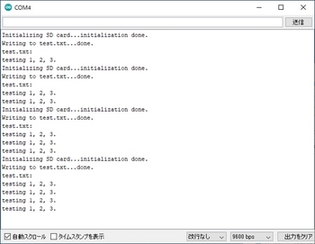
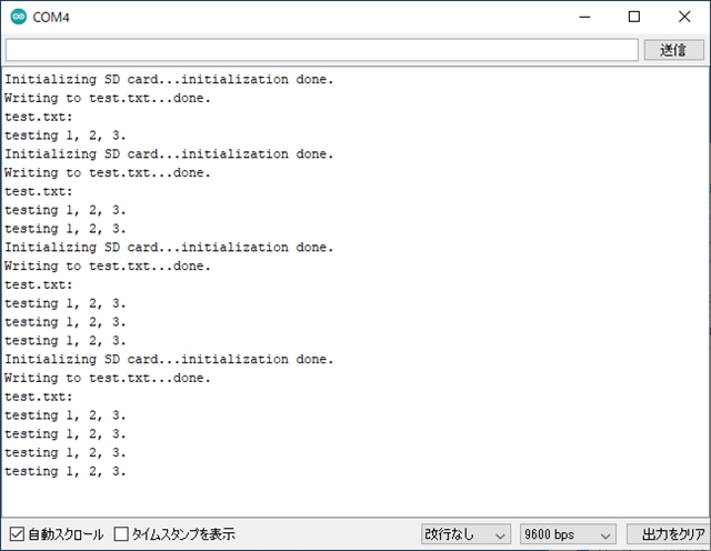
最初にシリアルモニタを立ち上げたときに1行目が記入され、以降、Arduino Pro Miniボードのリセットボタンを押すごとに"testing 1, 2, 3."の文字列が1行ずつ増えています。
#ArduinoでSDカード情報を取得する
次にArduinoからSDカードへファイルの読み書きをしたいと思います。
ブレッドボードの配線は同じで、スケッチだけ変えます。
【スケッチ】
SDカードにファイルを読み書きする、サンプルスケッチを試してみます。
Arduino IDEから
ファイル>スケッチ例>SD>ReadWrite
スケッチのCS(SS)ピン番号を4→10に変更しています。
/* SD card read/write This example shows how to read and write data to and from an SD card file The circuit: SD card attached to SPI bus as follows: ** MOSI - pin 11 ** MISO - pin 12 ** CLK - pin 13 ** CS - pin 4 (for MKRZero SD: SDCARD_SS_PIN) created Nov 2010 by David A. Mellis modified 9 Apr 2012 by Tom Igoe This example code is in the public domain. */ /******************************************************************************* テスト用SDカードリードライトプログラム ++++++ note ++++++ ・Arduino Pro Mini用にSSピンを変更 ・SDカードにテキストファイルを読み書きするプログラム *******************************************************************************/ #include#include File myFile; void setup() { // Open serial communications and wait for port to open: Serial.begin(9600); while (!Serial) { ; // wait for serial port to connect. Needed for native USB port only } Serial.print("Initializing SD card..."); if (!SD.begin(10)) { //4→10に変更 Serial.println("initialization failed!"); while (1); } Serial.println("initialization done."); // open the file. note that only one file can be open at a time, // so you have to close this one before opening another. myFile = SD.open("test.txt", FILE_WRITE); // if the file opened okay, write to it: if (myFile) { Serial.print("Writing to test.txt..."); myFile.println("testing 1, 2, 3."); // close the file: myFile.close(); Serial.println("done."); } else { // if the file didn't open, print an error: Serial.println("error opening test.txt"); } // re-open the file for reading: myFile = SD.open("test.txt"); if (myFile) { Serial.println("test.txt:"); // read from the file until there's nothing else in it: while (myFile.available()) { Serial.write(myFile.read()); } // close the file: myFile.close(); } else { // if the file didn't open, print an error: Serial.println("error opening test.txt"); } } void loop() { // nothing happens after setup }
最初にシリアルモニタを立ち上げたときに1行目が記入され、以降、Arduino Pro Miniボードのリセットボタンを押すごとに"testing 1, 2, 3."の文字列が1行ずつ増えています。
ArduinoでSDカード情報を取得する [Arduino]
(2021.1.1更新)
#とりあえず、上手くいかなかったことも後学のためと思い、掲載します。
#後日、解決したらタイトルも変えて、更新したいと思います。
(2021.1.9更新) Papilioシリーズ、中止しました
”Papilioでカメラ画像を転送する”シリーズをやっていますが、まぁまぁそんなにスムーズにいくわけもなく、いい感じで行き詰っております orz。。。
なかなか実績もないところもあり、Papilio or ZPUinoのどちらで間違えているか?切り分けもままならぬ状況なので、一旦、Arduinoで試してみようと思います。
ArduinoからSDカードへファイルを読み書きさせたいのですが、まず最初はタイトル通りにArduinoからSDカードの情報を取得してみたいと思います。
SDカードのIOは3.3Vで、Arduino UNOは5Vなのでそのままでは使えません。そのため今回はArduino Pro Mini(3.3V, 8MHz)を使います。
ArduinoとSDカードのやり取りはSPIというインターフェースで行われます。
SPIとは、。。。。。。。
ANALOGDEVICES社の技術資料ページのリンクを貼っておきます。
"https://www.analog.com/jp/analog-dialogue/articles/introduction-to-spi-interface.html#"
SDカードソケットを調達します。これ↓です。
SDカード配線引出基板
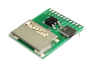
"https://akizukidenshi.com/catalog/g/gK-10967/"
DIP化されるのでブレッドボードで使用可能になります。
USBコネクタは電源供給用です(基板上で5V→3.3Vに変換)。
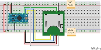
【配線図】
E38394E383B3E9858DE7BDAEE59BB3.jpg)
Arduino Pro Mini (pin) --- SDカード(基板)
SCK(13) CLK(CLK)
MISO(12) D0/DAT0(D0)
MOSI(11) DI/CMD(CMD)
SS(10) CS/CD/DAT3(D3)
【スケッチ】
最初にSDカード情報をコンソール画面に表示する、サンプルスケッチを試してみます。
Arduino IDEから
ファイル>スケッチ例>SD>CardInfo
スケッチのCS(SS)ピン番号を4→10に変更しています。
手元にあった512MBのSDカードを使って試してみましたが、動作がかなり不安定です。カード情報を取れたり、取れなかったり。
Arduino Pro Miniボードのリセットを何度か押して、コンソール画面に表示させます。
配線長とかも不安定の要素らしいので、出来るだけ短くした方が良いそうです。
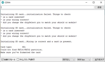
とりあえずSDカードと認識しても”パーティションが無い!”とか不完全な感じです。
”Windows標準のフォーマットではなくてSDフォーマッターを使用してフォーマットした方が良い”とのネット記事も読んだので試してみましたが、状況は変わらないです。。。(FAT16 or FAT32でフォーマットしているんですけどね)
SDアソシエーション
"https://www.sdcard.org/jp/index.html"
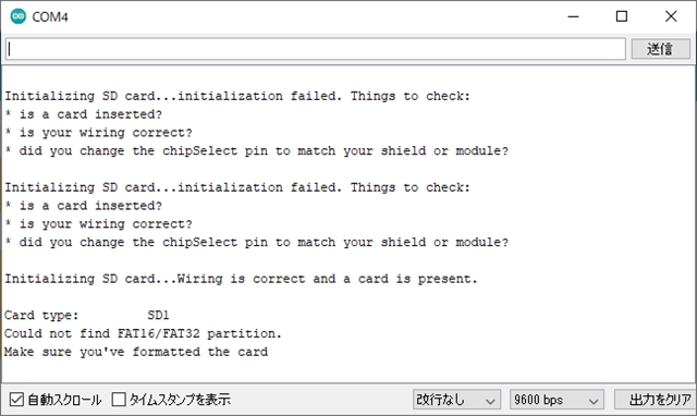
その後、Arduino Pro Miniボードのリセットを連打しても、
Initializing SD card...initialization failed. Things to check:
* is a card inserted?
* is your wiring correct?
* did you change the chipSelect pin to match your shield or module?
のメッセージしか出ないですね。”配線を見直せ”と言われても4本しかないですからねー。
感覚的には20回に1回くらいでSDカードを認識するメッセージも出ますが、やっぱり"パーティションが無い"と言われて。。。
いずれにせよ、ちょっとこのままでは使い物にならないわけで、次の手を考えてみたいと思います。
=========================================================
(2021.1.1更新)
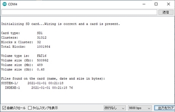
前回までの不安定動作が解消し、カード情報を取得することが出来たので更新します。
やったことは2つ、①電源強化と②パスコンの実装です。
①はこれまでもSDカードにアクセスした際に電圧降下も観測しなかったので”ちょっと違うかもしれない”とは思いつつ、電源周りを見直すことも一つの案として実施しました。
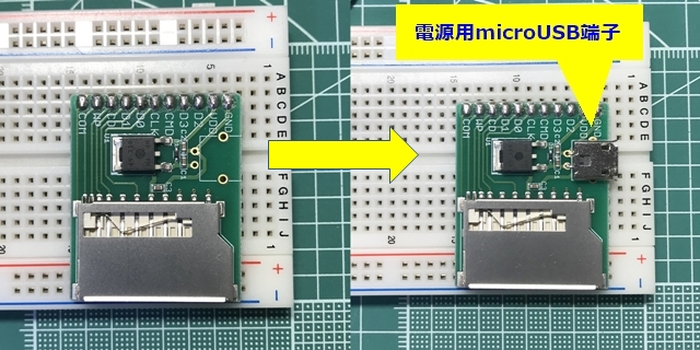
SDカード配線引出基板にはmicroUSB端子を利用して外部から5V電源を入力することが可能です。これまではArduino Pro Miniと同系統で3.3Vを供給していたため、電源ラインを分ける形にしました。
ただ結果的に、想定通りに問題解決策にはなりませんでした。
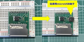
基板にmicroUSB端子を追加実装しています。
②パスコンの実装
電源とGNDの間に0.1μFのパスコンを実装しました(いわゆる、お守り代わりですが)。
実は前回もやって上手くいかなかったのですが、今回はブレッドボードに挿す感触が前回より強め?のような気がして。。。
結果、電源ラインもmicroUSB端子からこれまでと同様にArduino Pro Miniと同系統で3.3Vを供給しても安定動作して、パスコンが問題解決策になりました。
Arduino Pro Miniボードのリセットを押して、コンソール画面に表示させます。
(2021.1.9更新) Papilioシリーズ、中止しました
ArduinoからSDカードへファイルを読み書きさせたいのですが、まず最初はタイトル通りにArduinoからSDカードの情報を取得してみたいと思います。
SDカードのIOは3.3Vで、Arduino UNOは5Vなのでそのままでは使えません。そのため今回はArduino Pro Mini(3.3V, 8MHz)を使います。
ArduinoとSDカードのやり取りはSPIというインターフェースで行われます。
SPIとは、。。。。。。。
ANALOGDEVICES社の技術資料ページのリンクを貼っておきます。
"https://www.analog.com/jp/analog-dialogue/articles/introduction-to-spi-interface.html#"
SDカードソケットを調達します。これ↓です。
SDカード配線引出基板

"https://akizukidenshi.com/catalog/g/gK-10967/"
DIP化されるのでブレッドボードで使用可能になります。
USBコネクタは電源供給用です(基板上で5V→3.3Vに変換)。
【配線図】
E38394E383B3E9858DE7BDAEE59BB3.jpg)
Arduino Pro Mini (pin) --- SDカード(基板)
SCK(13) CLK(CLK)
MISO(12) D0/DAT0(D0)
MOSI(11) DI/CMD(CMD)
SS(10) CS/CD/DAT3(D3)

【スケッチ】
最初にSDカード情報をコンソール画面に表示する、サンプルスケッチを試してみます。
Arduino IDEから
ファイル>スケッチ例>SD>CardInfo
スケッチのCS(SS)ピン番号を4→10に変更しています。
/*
SD card test
This example shows how use the utility libraries on which the'
SD library is based in order to get info about your SD card.
Very useful for testing a card when you're not sure whether its working or not.
The circuit:
SD card attached to SPI bus as follows: >次のようにSPIバスに接続されたSDカード
** MOSI - pin 11 on Arduino Uno/Duemilanove/Diecimila >Arduino Uno / Duemilanove / Diecimilaのピン11
** MISO - pin 12 on Arduino Uno/Duemilanove/Diecimila
** CLK - pin 13 on Arduino Uno/Duemilanove/Diecimila
** CS - depends on your SD card shield or module. >SDカードのシールドまたはモジュールによって異なります。
Pin 4 used here for consistency with other Arduino examples
>他のArduinoの例との一貫性のためにここで使用されるピン4
created 28 Mar 2011
by Limor Fried
modified 9 Apr 2012
by Tom Igoe
*/
/*******************************************************************************
テスト用SDカード情報取得プログラム
++++++ note ++++++
・Arduino Pro Mini用にSSピンを変更
・SDカード情報をコンソール画面に表示するプログラム
*******************************************************************************/
// include the SD library:
#include
#include
// set up variables using the SD utility library functions:
Sd2Card card;
SdVolume volume;
SdFile root;
// change this to match your SD shield or module;
// Arduino Ethernet shield: pin 4
// Adafruit SD shields and modules: pin 10
// Sparkfun SD shield: pin 8
// MKRZero SD: SDCARD_SS_PIN
//const int chipSelect = 4;
//↓変更
// Arduino Pro Mini: pin 10
const int chipSelect = 10;
void setup() {
// Open serial communications and wait for port to open:
Serial.begin(9600);
while (!Serial) {
; // wait for serial port to connect. Needed for native USB port only
}
Serial.print("\nInitializing SD card...");
// we'll use the initialization code from the utility libraries
// since we're just testing if the card is working!
if (!card.init(SPI_HALF_SPEED, chipSelect)) {
Serial.println("initialization failed. Things to check:");
Serial.println("* is a card inserted?");
Serial.println("* is your wiring correct?");
Serial.println("* did you change the chipSelect pin to match your shield or module?");
while (1);
} else {
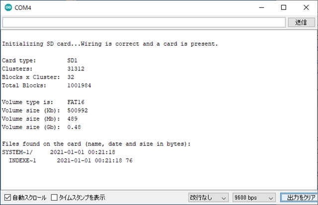
Serial.println("Wiring is correct and a card is present.");
}
// print the type of card
Serial.println();
Serial.print("Card type: ");
switch (card.type()) {
case SD_CARD_TYPE_SD1:
Serial.println("SD1");
break;
case SD_CARD_TYPE_SD2:
Serial.println("SD2");
break;
case SD_CARD_TYPE_SDHC:
Serial.println("SDHC");
break;
default:
Serial.println("Unknown");
}
// Now we will try to open the 'volume'/'partition' - it should be FAT16 or FAT32
if (!volume.init(card)) {
Serial.println("Could not find FAT16/FAT32 partition.\nMake sure you've formatted the card");
while (1);
}
Serial.print("Clusters: ");
Serial.println(volume.clusterCount());
Serial.print("Blocks x Cluster: ");
Serial.println(volume.blocksPerCluster());
Serial.print("Total Blocks: ");
Serial.println(volume.blocksPerCluster() * volume.clusterCount());
Serial.println();
// print the type and size of the first FAT-type volume
uint32_t volumesize;
Serial.print("Volume type is: FAT");
Serial.println(volume.fatType(), DEC);
volumesize = volume.blocksPerCluster(); // clusters are collections of blocks
volumesize *= volume.clusterCount(); // we'll have a lot of clusters
volumesize /= 2; // SD card blocks are always 512 bytes (2 blocks are 1KB)
Serial.print("Volume size (Kb): ");
Serial.println(volumesize);
Serial.print("Volume size (Mb): ");
volumesize /= 1024;
Serial.println(volumesize);
Serial.print("Volume size (Gb): ");
Serial.println((float)volumesize / 1024.0);
Serial.println("\nFiles found on the card (name, date and size in bytes): ");
root.openRoot(volume);
// list all files in the card with date and size
root.ls(LS_R | LS_DATE | LS_SIZE);
}
void loop(void) {
}
手元にあった512MBのSDカードを使って試してみましたが、動作がかなり不安定です。カード情報を取れたり、取れなかったり。
Arduino Pro Miniボードのリセットを何度か押して、コンソール画面に表示させます。
配線長とかも不安定の要素らしいので、出来るだけ短くした方が良いそうです。
とりあえずSDカードと認識しても”パーティションが無い!”とか不完全な感じです。
”Windows標準のフォーマットではなくてSDフォーマッターを使用してフォーマットした方が良い”とのネット記事も読んだので試してみましたが、状況は変わらないです。。。(FAT16 or FAT32でフォーマットしているんですけどね)
SDアソシエーション
"https://www.sdcard.org/jp/index.html"
その後、Arduino Pro Miniボードのリセットを連打しても、
Initializing SD card...initialization failed. Things to check:
* is a card inserted?
* is your wiring correct?
* did you change the chipSelect pin to match your shield or module?
のメッセージしか出ないですね。”配線を見直せ”と言われても4本しかないですからねー。
感覚的には20回に1回くらいでSDカードを認識するメッセージも出ますが、やっぱり"パーティションが無い"と言われて。。。
いずれにせよ、ちょっとこのままでは使い物にならないわけで、次の手を考えてみたいと思います。
=========================================================
(2021.1.1更新)
前回までの不安定動作が解消し、カード情報を取得することが出来たので更新します。
やったことは2つ、①電源強化と②パスコンの実装です。
①はこれまでもSDカードにアクセスした際に電圧降下も観測しなかったので”ちょっと違うかもしれない”とは思いつつ、電源周りを見直すことも一つの案として実施しました。
SDカード配線引出基板にはmicroUSB端子を利用して外部から5V電源を入力することが可能です。これまではArduino Pro Miniと同系統で3.3Vを供給していたため、電源ラインを分ける形にしました。
ただ結果的に、想定通りに問題解決策にはなりませんでした。
基板にmicroUSB端子を追加実装しています。
②パスコンの実装
電源とGNDの間に0.1μFのパスコンを実装しました(いわゆる、お守り代わりですが)。
実は前回もやって上手くいかなかったのですが、今回はブレッドボードに挿す感触が前回より強め?のような気がして。。。
結果、電源ラインもmicroUSB端子からこれまでと同様にArduino Pro Miniと同系統で3.3Vを供給しても安定動作して、パスコンが問題解決策になりました。

Arduino Pro Miniボードのリセットを押して、コンソール画面に表示させます。
Arduinoで距離を測る(2)【赤外線測距センサ with XBee(動作確認)】 [Arduino]
せっかくなので、超音波測距センサのときと同じように、測定したアナログ値をバイナリデータとしてXBee間でシリアル通信して、PCのシリアルモニタに表示をさせます。
赤外線測距センサの「GP2Y0A21YK」の測定レンジは10cm~80cmですので、測定レンジを外れたら"Out of Range"と表示します。
【スケッチ】
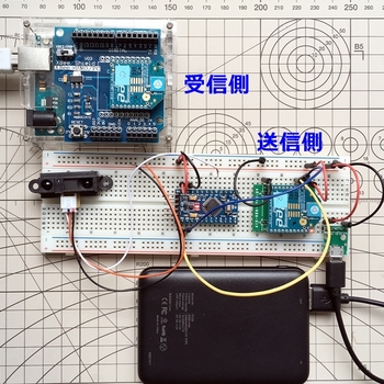
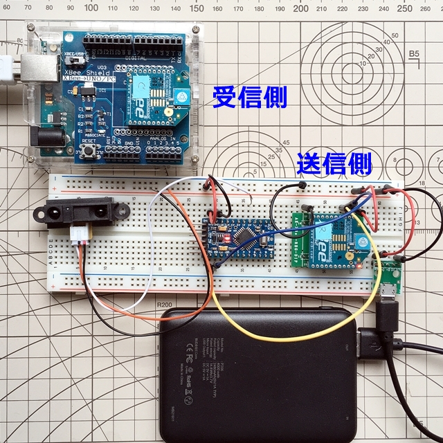
<送信側>
<受信側>
赤外線測距センサの「GP2Y0A21YK」の測定レンジは10cm~80cmですので、測定レンジを外れたら"Out of Range"と表示します。
【スケッチ】
<送信側>
/*******************************************************************************
赤外線距離センサ(GP2Y0A21YK)用XBeeトランスミッタ

++++++ note ++++++
シャープ測距モジュール(GP2Y0A21YK)用にArduinoProMini-XBee送信機

*******************************************************************************/
// These constants won't change. They're used to give names to the pins used:
const int analogInPin = A0;               //A0をアナログ入力ピンに指定
int sensorValue = 0;

// the setup routine runs once when you press reset:初期化(電源投入/リセット時1回のみ実行)
void setup() {
  // initialize serial communication at 9600 bits per second:
  Serial.begin(9600);                     //9600bpsでシリアルポートを開く
}

// the loop routine runs over and over again forever: main loop
void loop() {
  sensorValue = analogRead(analogInPin);  //アナログ入力ピン(A0)の値を読む
  sendIntData(sensorValue);
  delay(100);
}

 // int型のデータを送信する関数
void sendIntData(int value) {
  Serial.write('H'); // ヘッダの送信
  Serial.write(lowByte(value));   // 下位バイトの送信
  Serial.write(highByte(value));  // 上位バイトの送信
}
<受信側>
/*******************************************************************************
赤外線距離センサ(GP2Y0A21YK)用XBeeレシーバ

++++++ note ++++++
シャープ測距モジュール(GP2Y0A21YK)用にArduinoUNO-XBee受信機

*******************************************************************************/
int recv_data;                                    //受信データ
const float Vcc = 5.0;                            //電源電圧(定数)
float range_volt;                                 //出力電圧
float range_data;                                 //距離

// 初期化(電源投入/リセット時1回のみ実行):
void setup() {
  Serial.begin(9600);                             //9600bpsでシリアルポートを開く
}
// main loop:
void loop() {
  // 受信バッファに3バイト(ヘッダ+int)以上のデータが着ているか確認
  if ( Serial.available() >= sizeof('H') + sizeof(int) ) {
    // ヘッダの確認
    if ( Serial.read() == 'H' ){
      int low = Serial.read();                    //下位バイトの読み取り
      int high = Serial.read();                   //上位バイトの読み取り
      recv_data = makeWord(high,low);             //上位バイトと下位バイトを合体させてint型データを復元
    }

  // 受信データから表示させる距離データを作成
  range_volt = Vcc * recv_data / 1023;            //アナログピンから読み取った値を元の出力電圧値に戻す

  // 出力電圧から距離データを作成
//range_data = 27.289 * pow(range_volt, -1.202);  //【データシート】距離を計算(累乗近似) pow:べき乗
  range_data = 26.123 * pow(range_volt, -1.106);  //【実測】距離を計算(累乗近似) pow:べき乗

  // 距離データの表示 range_dataの値をハード・シリアルへ出力する(Arduino→PCモニタ)
    if((range_data >= 10) && (range_data <= 80)){   //range_dataが10以上80以下ならば、距離を表示する
      Serial.print("Range= ");
      Serial.print(range_data);                     //距離を表示
      Serial.println("[cm]");                       //単位はcm
    }
    else{                                           //range_dataがそれ以外ならば、Out of Rangeと表示する
      Serial.println("Out of Range");
    }
  }
}
Arduinoで距離を測る(2)【赤外線測距センサ】 [Arduino]
Arduinoで距離を測る(1)で超音波測距センサを使ってみました。XBee経由で遠隔からデータを取得することもできました。
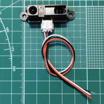
次は、赤外線距離センサの「GP2Y0A21YK0F」を使います。
とりあえず、赤外線の距離センサと言ったらコレ!、というくらいネットでもヒットしますので定番なんでしょうね。これです↓
シャープ測距モジュール GP2Y0A21YK0F
"http://akizukidenshi.com/catalog/g/gI-02551/"
今回は単純に動作させてみるだけなので、Arduino UNOに接続してPCのシリアルモニタで表示できるようにしたいと思います。
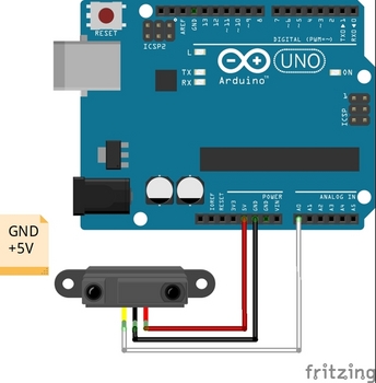
【配線図】
【スケッチ】
Arduino IDEから
ファイル>スケッチ例>01.Basics>AnalogReadSerial
のサンプルプログラムを改修して作成しました。
センサから出力されたアナログ値から距離を求める数式ですが、データシートのグラフと実測値を用いて、Excelにて累乗近似式で求めました。
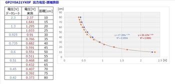
距離が離れれば離れるほど計測結果はだいぶ怪しくなってきます。理由は距離に対する出力電圧の変化が小さいためだと思います。実用的には50cm未満のところで使うのが良いと思います。測定中の数値のバラつきもかなりありますので、距離を正確に計測するという用途よりも”ざっくりと20cm以下になったらブレーキをかけたい”とか、だいたいの近い距離まで接近したら何か処理をさせる、というような使い方が良いと思います。
#超音波測距センサとしてメジャーであれば、これから使う機会もあるのでしょうけど、個人的にはちょっと使いづらいデバイスだなー、とは思っています。。。
次は、赤外線距離センサの「GP2Y0A21YK0F」を使います。
とりあえず、赤外線の距離センサと言ったらコレ!、というくらいネットでもヒットしますので定番なんでしょうね。これです↓
シャープ測距モジュール GP2Y0A21YK0F

"http://akizukidenshi.com/catalog/g/gI-02551/"
今回は単純に動作させてみるだけなので、Arduino UNOに接続してPCのシリアルモニタで表示できるようにしたいと思います。
【配線図】

【スケッチ】
Arduino IDEから
ファイル>スケッチ例>01.Basics>AnalogReadSerial
のサンプルプログラムを改修して作成しました。
/*
  AnalogReadSerial

  Reads an analog input on pin 0, prints the result to the Serial Monitor.
  Graphical representation is available using Serial Plotter (Tools > Serial Plotter menu).
  Attach the center pin of a potentiometer to pin A0, and the outside pins to +5V and ground.

  This example code is in the public domain.

  http://www.arduino.cc/en/Tutorial/AnalogReadSerial
*/
/*******************************************************************************
赤外線距離センサ(GP2Y0A21YK) サンプルプログラム

++++++ note ++++++
・シャープ測距モジュール GP2Y0A21YK
・測定した距離をコンソール画面に表示するプログラム
・測距範囲:10~80cm

*******************************************************************************/
const float Vcc = 5.0;                            //電源電圧(定数)
float range_volt;                                 //出力電圧
float range_data;                                 //距離

// the setup routine runs once when you press reset:初期化(電源投入/リセット時1回のみ実行)
void setup() {
  // initialize serial communication at 9600 bits per second:
  Serial.begin(9600);                             //9600bpsでシリアルポートを開く
}

// the loop routine runs over and over again forever: main loop
void loop() {
  int sensorValue = analogRead(A0);               //read the input on analog pin 0:
  range_volt = Vcc * sensorValue / 1023;          //アナログピンから読み取った値を元の出力電圧値に戻す

// 出力電圧から距離データを作成
//range_data = 27.289 * pow(range_volt, -1.202);  //【データシート】距離を計算(累乗近似) pow:べき乗
  range_data = 26.123 * pow(range_volt, -1.106);  //【実測】距離を計算(累乗近似) pow:べき乗

// 距離データの表示 range_dataの値をハード・シリアルへ出力する(Arduino→PCモニタ)
  Serial.print("Output Voltage= ");
  Serial.print(range_volt);                       //出力電圧を表示
  Serial.print("[V], ");
  Serial.print("Range= ");
  Serial.print(range_data);                       //距離を表示
  Serial.println("[cm]");                         //単位はcm
  delay(500);                                     //シリアルポートを溢れさせないように ※delay():単位ms
}
センサから出力されたアナログ値から距離を求める数式ですが、データシートのグラフと実測値を用いて、Excelにて累乗近似式で求めました。
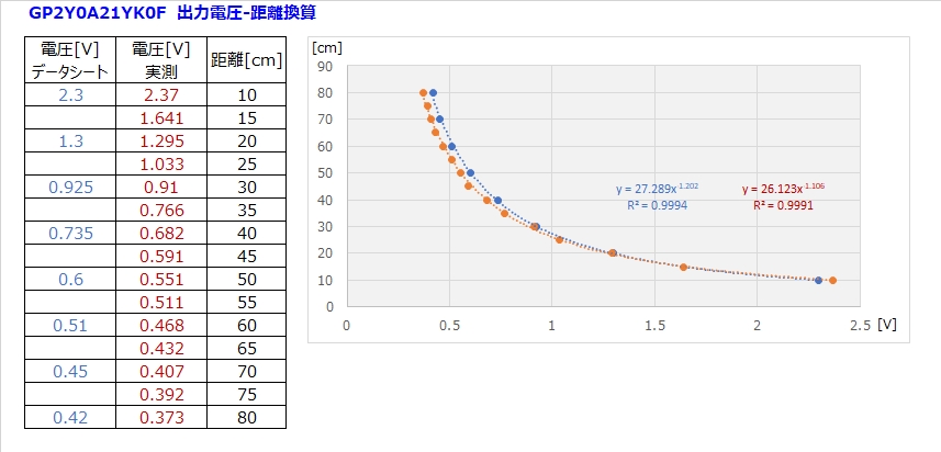
距離が離れれば離れるほど計測結果はだいぶ怪しくなってきます。理由は距離に対する出力電圧の変化が小さいためだと思います。実用的には50cm未満のところで使うのが良いと思います。測定中の数値のバラつきもかなりありますので、距離を正確に計測するという用途よりも”ざっくりと20cm以下になったらブレーキをかけたい”とか、だいたいの近い距離まで接近したら何か処理をさせる、というような使い方が良いと思います。
#超音波測距センサとしてメジャーであれば、これから使う機会もあるのでしょうけど、個人的にはちょっと使いづらいデバイスだなー、とは思っています。。。


