Arduinoでデータロガーを作る【温度センサ+SDカード】 [Arduino]
前回までで、
・SDカードにファイルを読み書きする #ArduinoでSDカードにファイルを読み書きする
・温度を測定する #Arduinoで温度を測る【温度センサ】
ことができましたので、これを組み合わせて温度データをSDカードに書き込むデータロガーを作りたいと思います。
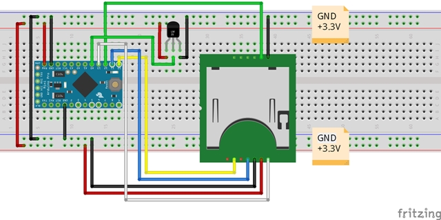
【配線図】
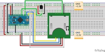
【スケッチ】
ネットも参考にすると、もう少しスマートな記述もありますが、今の自分の理解レベルと少々乖離している感もあったので、まずはベタな書き方ですが載せてみます。
今後スキルが上がれば、改版したいと思っています。
①float(浮動小数点)形式、②String(文字列)形式の両方を記述していますが、下記では①をコメントアウトして、②を有効にしています。
上記でもデータは保存できたのですが、少々残念なことに、データを取得したタイムスタンプが無いんですねー。。。
なので、次はRTCを使ってタイムスタンプとセットでデータを保存できるようにしたいと思います。

・SDカードにファイルを読み書きする #ArduinoでSDカードにファイルを読み書きする
・温度を測定する #Arduinoで温度を測る【温度センサ】
ことができましたので、これを組み合わせて温度データをSDカードに書き込むデータロガーを作りたいと思います。
【配線図】
【スケッチ】
ネットも参考にすると、もう少しスマートな記述もありますが、今の自分の理解レベルと少々乖離している感もあったので、まずはベタな書き方ですが載せてみます。
今後スキルが上がれば、改版したいと思っています。
①float(浮動小数点)形式、②String(文字列)形式の両方を記述していますが、下記では①をコメントアウトして、②を有効にしています。
/******************************************************************************* SDカードデータロガー ++++++ note ++++++ ・測定した温度をコンソール画面に表示およびSDカードにデータ保存するプログラム ・Arduino Pro Mini(3.3V, 8MHz) ・温度センサ LM61BIZ(測定範囲:-25℃~+85℃) ・①float(浮動小数点)形式でも②String(文字列)形式でも出力結果は同じ *******************************************************************************/ #include#include File myFile; const float Vcc = 3.3; //電源電圧(定数) float temp_volt; //出力電圧 float temp_data; //温度 // the setup routine runs once when you press reset:初期化(電源投入/リセット時1回のみ実行) void setup() { // Open serial communications and wait for port to open: Serial.begin(9600); //9600bpsでシリアルポートを開く while (!Serial) { ; // wait for serial port to connect. Needed for native USB port only } //SDカードの初期設定 Serial.print("Initializing SD card..."); if (!SD.begin(10)) { //4→10に変更 Serial.println("initialization failed!"); while (1); } Serial.println("initialization done."); } // the loop routine runs over and over again forever: main loop void loop() { int sensorValue = analogRead(A0); //read the input on analog pin 0: temp_volt = Vcc * sensorValue / 1023; //アナログピンから読み取った値を元の出力電圧値に戻す // 出力電圧から温度データを作成 temp_data = (temp_volt - 0.6) / 0.01; //【データシート】T[℃] = (Vo - 0.6) / 0.01 // 温度データをコンソール画面に表示 ※2種類記載 /* ①float(浮動小数点)形式で表示 Serial.print(temp_data); //温度を表示 Serial.println("[℃]"); //単位は℃ */ // ②String(文字列)形式で表示 String dataString = ""; dataString += String(temp_data); dataString += "[℃]"; Serial.println(dataString); //温度を表示、単位は℃ // SDカードに書き込む // open the file. note that only one file can be open at a time, // so you have to close this one before opening another. myFile = SD.open("tempdata.txt", FILE_WRITE); //"tempdata.txt"ファイルを書き込み用に開く //戻り値がファイル情報になり、myFile に受け渡す // ファイルに温度データを書き込み ※2種類記載 // if the file opened okay, write to it: if (myFile) { /* ①float(浮動小数点)形式で書き込み myFile.print(temp_data); myFile.println("[℃]"); */ // ②文字列(String)で書き込み myFile.println(dataString); // close the file: myFile.close(); //ファイルを閉じる } else { // if the file didn't open, print an error: Serial.println("error opening tempdata.txt"); } delay(1000); //1秒単位 ※delay():単位ms }
上記でもデータは保存できたのですが、少々残念なことに、データを取得したタイムスタンプが無いんですねー。。。
なので、次はRTCを使ってタイムスタンプとセットでデータを保存できるようにしたいと思います。
Arduinoで温度を測る [Arduino]
Arduinoで温度を測ります!
使うのは、温度センサの「LM61BIZ」です。
これです↓
高精度IC温度センサLM61BIZ
.JPG)
※以前に秋月電子で購入したのですが、メーカ都合により現在では販売されていないようです。
TI社の半導体製品が生産終了でないのに在庫限りです。どうしてですか?/TIのIC単体を購入できませんがどうしてですか?
"https://akizukidenshi.com/catalog/faq/goodsfaq.aspx?goods=I-09691"
【配線図】
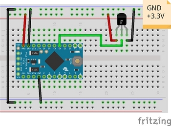
【スケッチ】
データシートを見ると
Vo = (+10mV/℃ × T℃)+ 600mV
とありますので、温度T℃を求めるためには、
T℃ = (Vo - 0.6[V]) / 0.01[V]
で求まります。
スケッチは以前に赤外線測距センサで作成したものを少し修正すればOKです。
/*
  AnalogReadSerial

  Reads an analog input on pin 0, prints the result to the Serial Monitor.
  Graphical representation is available using Serial Plotter (Tools > Serial Plotter menu).
  Attach the center pin of a potentiometer to pin A0, and the outside pins to +5V and ground.

  This example code is in the public domain.

  http://www.arduino.cc/en/Tutorial/AnalogReadSerial
*/
/*******************************************************************************
温度センサ(LM61BIZ) サンプルプログラム
++++++ note ++++++
・温度センサ LM61BIZ
・測定した温度をコンソール画面に表示するプログラム
・測定範囲:-25℃~+85℃

*******************************************************************************/
const float Vcc = 3.3;                   //電源電圧(定数)
float temp_volt;                         //出力電圧
float temp_data;                         //温度

// the setup routine runs once when you press reset:初期化(電源投入/リセット時1回のみ実行)
void setup() {
  // initialize serial communication at 9600 bits per second:
  Serial.begin(9600);                    //9600bpsでシリアルポートを開く
}

// the loop routine runs over and over again forever: main loop
void loop() {
  int sensorValue = analogRead(A0);      //read the input on analog pin 0:
  temp_volt = Vcc * sensorValue / 1023;  //アナログピンから読み取った値を元の出力電圧値に戻す

// 出力電圧から温度データを作成
  temp_data = (temp_volt - 0.6) / 0.01;  //【データシート】T[℃] = (Vo - 0.6) / 0.01

// 温度データの表示 temp_dataの値をハード・シリアルへ出力する(Arduino→PCモニタ)
  Serial.print(temp_data);               //温度を表示
  Serial.println("[℃]");                //単位は℃
  delay(1000);                           //1秒単位(シリアルポートを溢れさせないように) ※delay():単位ms
}
ArduinoでGPS情報を取得する [Arduino]
SDカードシリーズはいろいろと物品調達の準備があるため、その間に別のことやりたいと思います。
”ArduinoでGPS情報を取得する”です。
これもいずれはやっておきたかったことなので、このタイミングで試してみたいと思います。
GPSモジュールは秋月電子のを使います。
ググると、たくさんの製作記事がヒットするので情報には困らないと思います。
GPS受信機キット 1PPS出力付き「みちびき」3機受信対応

"https://akizukidenshi.com/catalog/g/gK-09991/"
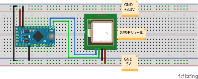
GPSモジュールの電源は5Vですが、データIOは3.3Vです。そのため今回はArduino Pro Mini(3.3V, 8MHz)を使います。
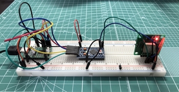
【配線図】

【スケッチ】
最初にGPSモジュールからの情報をコンソール画面に表示する、サンプルスケッチを試してみます。
Arduino IDEから
ファイル>スケッチ例>SoftwareSerial>SoftwareSerialExample
シアルポートのデータ転送レートを変更しています。
もちろん、シリアルモニタともデータ転送レートは一致させるのですが、9600以外では文字化けしてしまい、うまく表示することが出来ませんでした。
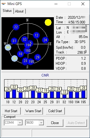
電源を入れるとLEDが点灯してGPSを捕捉し始めます。
コールドスタートと言って、まっさらな状態からだと40~90秒くらいでGPSを捕捉するようです。捕捉できたらLEDは1秒周期で点滅を始めます。
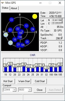
キットに付属のソフトウェア(MiniGPS)でデータを受けると、捕捉したGPSの数や緯度経度、時刻とかの情報を表示させることができます。
”ArduinoでGPS情報を取得する”です。
これもいずれはやっておきたかったことなので、このタイミングで試してみたいと思います。
GPSモジュールは秋月電子のを使います。
ググると、たくさんの製作記事がヒットするので情報には困らないと思います。
GPS受信機キット 1PPS出力付き「みちびき」3機受信対応
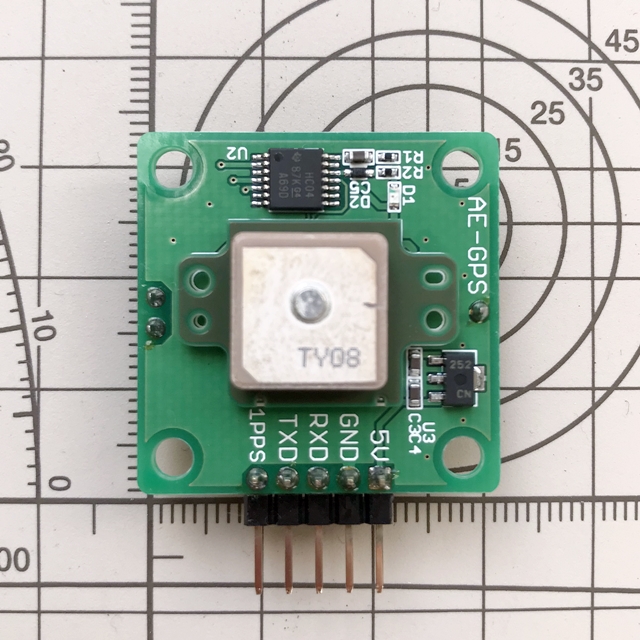
"https://akizukidenshi.com/catalog/g/gK-09991/"
GPSモジュールの電源は5Vですが、データIOは3.3Vです。そのため今回はArduino Pro Mini(3.3V, 8MHz)を使います。
【配線図】

【スケッチ】
最初にGPSモジュールからの情報をコンソール画面に表示する、サンプルスケッチを試してみます。
Arduino IDEから
ファイル>スケッチ例>SoftwareSerial>SoftwareSerialExample
シアルポートのデータ転送レートを変更しています。
もちろん、シリアルモニタともデータ転送レートは一致させるのですが、9600以外では文字化けしてしまい、うまく表示することが出来ませんでした。
/* Software serial multple serial test Receives from the hardware serial, sends to software serial. Receives from software serial, sends to hardware serial. The circuit: * RX is digital pin 10 (connect to TX of other device) * TX is digital pin 11 (connect to RX of other device) Note: Not all pins on the Mega and Mega 2560 support change interrupts, so only the following can be used for RX: 10, 11, 12, 13, 50, 51, 52, 53, 62, 63, 64, 65, 66, 67, 68, 69 Not all pins on the Leonardo and Micro support change interrupts, so only the following can be used for RX: 8, 9, 10, 11, 14 (MISO), 15 (SCK), 16 (MOSI). created back in the mists of time modified 25 May 2012 by Tom Igoe based on Mikal Hart's example This example code is in the public domain. */ /******************************************************************************* GPSテスト用シリアル通信プログラム ++++++ note ++++++ ・Arduino Pro Mini使用 ・スケッチデフォルトのボーレートで動作させると、GPSからの信号が文字化けする。 ⇒ボーレートを9600に変更(落とす)するとOK *******************************************************************************/ #includeSoftwareSerial mySerial(10, 11); // RX, TX void setup() { // Open serial communications and wait for port to open: //Serial.begin(57600); Serial.begin(9600); //ハードシリアルポートのデータ転送レートを9600bpsに設定 while (!Serial) { ; // wait for serial port to connect. Needed for native USB port only } Serial.println("Goodnight moon!"); //ハードシリアルポートから文字列出力 // set the data rate for the SoftwareSerial port //mySerial.begin(4800); mySerial.begin(9600); //ソフトシリアルポートのデータ転送レートを9600bpsに設定 mySerial.println("Hello, world?"); //ソフトシリアルポートから文字列出力 } void loop() { // run over and over if (mySerial.available()) { //もしソフトシリアルポートにデータあるならば Serial.write(mySerial.read()); //ソフトシリアルポートで読み込んだデータを //ハードシリアルポートに対して出力する } if (Serial.available()) { //もしハードシリアルポートにデータがあるならば mySerial.write(Serial.read()); //ハードシリアルポートで読み込んだデータを //ソフトシリアルポートに対して出力する } }
電源を入れるとLEDが点灯してGPSを捕捉し始めます。
コールドスタートと言って、まっさらな状態からだと40~90秒くらいでGPSを捕捉するようです。捕捉できたらLEDは1秒周期で点滅を始めます。
キットに付属のソフトウェア(MiniGPS)でデータを受けると、捕捉したGPSの数や緯度経度、時刻とかの情報を表示させることができます。
ArduinoでSDカードにファイルを読み書きする [Arduino]
ArduinoからSDカードの情報を取得できたので、
#ArduinoでSDカード情報を取得する
次にArduinoからSDカードへファイルの読み書きをしたいと思います。
ブレッドボードの配線は同じで、スケッチだけ変えます。
【スケッチ】
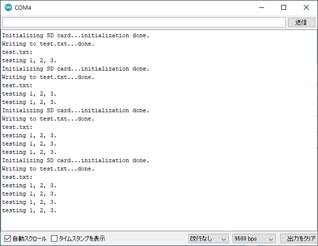
SDカードにファイルを読み書きする、サンプルスケッチを試してみます。
Arduino IDEから
ファイル>スケッチ例>SD>ReadWrite
スケッチのCS(SS)ピン番号を4→10に変更しています。
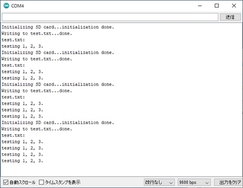
最初にシリアルモニタを立ち上げたときに1行目が記入され、以降、Arduino Pro Miniボードのリセットボタンを押すごとに"testing 1, 2, 3."の文字列が1行ずつ増えています。
#ArduinoでSDカード情報を取得する
次にArduinoからSDカードへファイルの読み書きをしたいと思います。
ブレッドボードの配線は同じで、スケッチだけ変えます。
【スケッチ】
SDカードにファイルを読み書きする、サンプルスケッチを試してみます。
Arduino IDEから
ファイル>スケッチ例>SD>ReadWrite
スケッチのCS(SS)ピン番号を4→10に変更しています。
/* SD card read/write This example shows how to read and write data to and from an SD card file The circuit: SD card attached to SPI bus as follows: ** MOSI - pin 11 ** MISO - pin 12 ** CLK - pin 13 ** CS - pin 4 (for MKRZero SD: SDCARD_SS_PIN) created Nov 2010 by David A. Mellis modified 9 Apr 2012 by Tom Igoe This example code is in the public domain. */ /******************************************************************************* テスト用SDカードリードライトプログラム ++++++ note ++++++ ・Arduino Pro Mini用にSSピンを変更 ・SDカードにテキストファイルを読み書きするプログラム *******************************************************************************/ #include#include File myFile; void setup() { // Open serial communications and wait for port to open: Serial.begin(9600); while (!Serial) { ; // wait for serial port to connect. Needed for native USB port only } Serial.print("Initializing SD card..."); if (!SD.begin(10)) { //4→10に変更 Serial.println("initialization failed!"); while (1); } Serial.println("initialization done."); // open the file. note that only one file can be open at a time, // so you have to close this one before opening another. myFile = SD.open("test.txt", FILE_WRITE); // if the file opened okay, write to it: if (myFile) { Serial.print("Writing to test.txt..."); myFile.println("testing 1, 2, 3."); // close the file: myFile.close(); Serial.println("done."); } else { // if the file didn't open, print an error: Serial.println("error opening test.txt"); } // re-open the file for reading: myFile = SD.open("test.txt"); if (myFile) { Serial.println("test.txt:"); // read from the file until there's nothing else in it: while (myFile.available()) { Serial.write(myFile.read()); } // close the file: myFile.close(); } else { // if the file didn't open, print an error: Serial.println("error opening test.txt"); } } void loop() { // nothing happens after setup }
最初にシリアルモニタを立ち上げたときに1行目が記入され、以降、Arduino Pro Miniボードのリセットボタンを押すごとに"testing 1, 2, 3."の文字列が1行ずつ増えています。